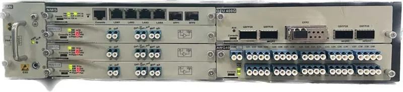
A WDM System (Wavelength Division Multiplexing System) enables efficient optical transmission by combining multiple wavelengths into a single fiber. Although setups may vary, a basic WDM System usually includes a management system, service cards, amplifiers, and multiplexers. Therefore, understanding these parts is essential for designing a stable network.
Management System: The Control Center of the WDM System
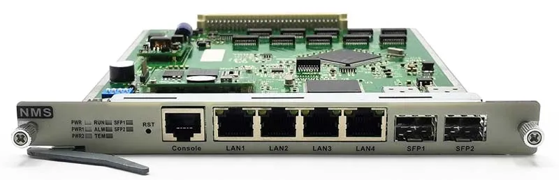
The management system is crucial because it monitors and controls all modules in the WDM System. It typically includes:
- One serial port
- Four electrical Ethernet ports
- Two optical ports for optical modules
However, the configuration can differ across models. For example, some systems may feature four optical ports and four electrical ports, which offers greater flexibility. In fact, HTF also supports custom configurations to meet special network demands. As a result, this system ensures stable operation while also providing reliable connectivity between devices.
Service Cards: The Core Engine of the WDM System
Service cards are the heart of any WDM System, as they process and transmit high-speed traffic. The sample setup uses a 400G service card with a 200G coherent module in the center. On both sides, there are two additional 200G optical modules.
Moreover, the coherent module offers TX and RX ports. Through optical fibers, these ports connect to another coherent module on a different device. Consequently, the system can deliver long-distance, high-capacity transmission while keeping performance stable.
Amplifiers: Enhancing Optical Signals Through the Route
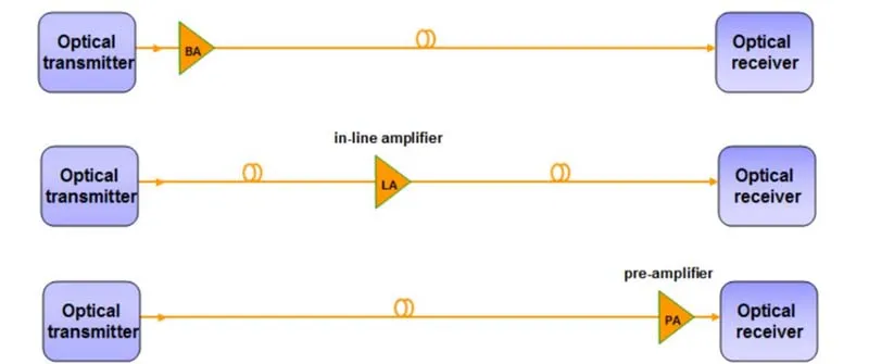
In a typical WDM System, optical amplifiers play a vital role in long-distance transmission. They strengthen weak optical signals and help maintain signal integrity. Therefore, a complete link usually includes three amplifier types:
- Booster Amplifier (BA)
Located at the transmitting end, the BA increases power before the signal enters the fiber.
Transition: As a result, the initial signal becomes strong enough for long-distance travel.
- Line Amplifier (LA)
Placed mid-span, the LA compensates for optical loss along the route.
Transition: However, the demonstration system does not include an LA.
- Pre-Amplifier (PA)
Installed at the receiving end, the PA boosts the incoming signal.
Transition: Therefore, the receiving module can detect weaker optical inputs with better accuracy.
Together, these amplifiers work in sequence and, consequently, help maintain stable performance across the entire link.
Multiplexer / Demultiplexer: Combining and Separating Wavelengths
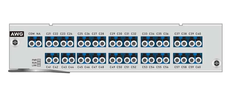
Finally, the system uses a 40-channel AWG multiplexer for both multiplexing and demultiplexing. At the transmitting end, the multiplexer combines multiple wavelengths into one fiber. At the receiving end, it separates those wavelengths again.
Moreover, because the AWG contains 40 channels, the WDM System supports long-term scalability. For example, an initial 400G service may occupy only one channel. Meanwhile, the remaining 39 channels can later carry an additional 39 × 400G of unperceived capacity expansion.
The components of a WDM System—management system, service cards, amplifiers, and multiplexers—work together to deliver efficient optical transmission. Consequently, by understanding how each part operates, users can design, optimize, and scale their systems with confidence.