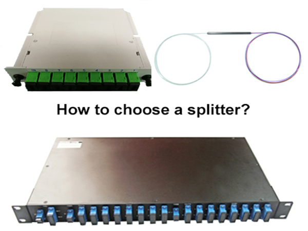
Optical splitters can be divided into box-type optical splitters, tray-type optical splitters, rack-mounted optical splitters, wall-mounted optical splitters, etc. according to the scope of application. Box-type optical splitters are generally used for optical fiber distribution boxes, etc.; tray-type optical splitters are generally used for ODF optical fiber distribution frames and optical cable transfer boxes in the computer room; rack-mounted optical splitters are installed in standard racks; wall-mounted optical splitters can install on the wall.
The optical splitter can be divided into two types: fusion tapered optical splitter and planar waveguide (PLC) optical splitter according to different manufacturing processes. Among them, the planar waveguide optical splitter (PLC) is widely used in FTTx and PON. The fusion tapered beam splitter is formed by fusing two or more optical fibers on the side; the planar waveguide beam splitter (PLC) is a micro-optical component type product that uses photolithography technology to form an optical waveguide on a dielectric or semiconductor substrate. Realize branch assignment function. The splitting principles of these two types of optical splitters are similar. They both achieve different branch amounts by changing the evanescent field coupling between the fibers (coupling degree, coupling length) and changing the fiber radius.
In addition, the beam splitter is divided into 1×2, 1×4, 1×8, 1×16, 1×32, 1×64, etc. according to the difference of the splitting ratio.
Note: On the semiconductor engraved board, the "Y"-shaped waveguide coupler is engraved by photolithography technology, and these "Y" waveguides are connected together to form a stepwise light splitting, which can realize 1×2, 1×4, 1×8. Split ratio of 1×16, 1×32, 1×64, etc.
How to choose among the many types of optical splitters above? We can first determine the application occasions and choose the appropriate optical splitter according to actual needs. For example, in applications where there are few branches and insensitive to light wavelengths (that is, only 1×2 or 1×4 is sufficient), select the fusion taper type Optical splitter: If it is used in FTTH and other applications that require multiple wavelengths (that is, 1×4 or more), choose a planar waveguide (PLC) optical splitter, because the planar waveguide (PLC) optical splitter is uniform and the channel is uniform.
Principles and planning of optical splitter
The split ratios of commonly used splitters are 1:2, 1:4, 1:8, 1:16, 1:32, and 1:64. If necessary, you can also choose 2: N optical splitter or non-uniform splitting splitter. When configuring the optical splitter, the maximum utilization rate of each PON port and optical splitter of the equipment must be considered. According to the user distribution density and distribution form, the optimal optical splitter combination and suitable installation position must be selected. There are two principles for the use of optical splitters: one is to use first-level splitting as much as possible, and the other is that the number of splitting levels does not exceed two. There are three reasons for using the first-level splitting: first, it can maximize PON utilization; second, it is convenient to diagnose faults; third, the system has high reliability.
How to place the splitter?
(1) Using the first-level splitting method, when the optical splitter is in the resident network, the splitter can be installed indoors or outdoors. The indoor installation locations include the central computer room of the community, the weak current well in the building, and the floor wiring box. The upper connecting optical cables of the optical splitter can come from three ways, namely, the first-level optical crossover box, the second-level optical crossover box or the optical fiber splitter box. This method is mainly suitable for the situation of large scale and high user density, such as high-rise residential buildings.
(2) If the secondary optical splitting method is adopted, the optical splitter can be installed on the backbone layer or the user distribution fiber optic cable layer. In the backbone layer, the splitter can be installed in the primary optical junction box, secondary optical junction box or inside the optical fiber distribution box. This method is suitable for situations where users are relatively scattered and new user optical cable networks.
How to use the splitter?
With the large-scale advancement of fiber to the home (FTTH) in China, the application of various optical passive products has developed rapidly. As the most core passive optical device in the construction of fiber to the home (FTTH), optical splitters are used to ensure communication links, which is important equipment for normal transmission. So how are optical splitters used in fiber to the home (FTTH) cabling?
Currently, primary and secondary spectroscopy is often used in engineering. For the first-level optical splitting method, the use of the optical splitter is generally divided into four situations: one is placed in the central office computer room; the other is placed in the cell computer room; the third is placed in the cell optical transfer box; the fourth is directly placed in the corridor. For the second-level splitter, the use of the splitter is generally divided into three situations: one is that the first-level splitter is placed in the central office room, and the second-level splitter is placed in the optical transfer box; the second is that the first-level splitter is placed next to the road. In the large-capacity optical crossover box, the secondary optical splitter is placed in the community optical crossover box; the third is the primary optical splitter is placed in the residential optical crossover box, and the secondary optical splitter is placed in the corridor.
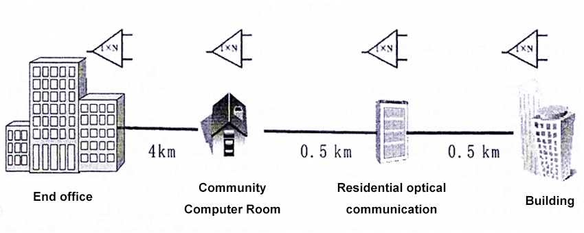
For example: suppose that the end office is 4km to the cell, 4.5km to the cell, 5km to the user building, there are 20 buildings in the cell, each building has 30 households, and all the drop-in optical cables in the building use drop-in optical cables, as shown below Shown.
(1) In the case of first-level optical splitting, the full coverage method is adopted, and each building is covered at a splitting ratio of 1:32. The number and length of the backbone optical cable and the distribution optical cable are counted (the number of optical cable cores is based on the actual production core Considering the number of users closest to the number of users, no statistics are made on the optical fiber cables from the corridor fiber distribution box to the user ONU, as shown in the following table.
|
Optical splitter placement position |
Number of backbone optical cables and cores |
Number of distribution optical cables and cores |
Required optical cables (core kilometers) |
|
Central office room |
No backbone optical cables |
20 pieces 32 cores 5km |
20*32*5=3200 |
|
Residential computer room |
1 piece 24 core 4km |
20 pieces 32 cores 0.5km |
24*4.5+32*0.5*20=428 |
|
Residential optical communication Box |
1 piece 24 core 4.5km |
20 pieces 32 cores 0.5km |
24*4.5+32*0.5*20=428 |
|
Building |
20 piece 4 cores 5km (no junction) |
- |
20*4*5=400 |
|
|
1 piece 24 cores 5km (distribution fiber optic cable is tandem in the cell room) |
20 pieces 4 cores 1km |
24*4+4*1*20=176 |
|
|
1 piece 24 cores 4.5km (distribution box optical cable is tandem within the optical exchange) |
20 pieces 4 cores 0.5km |
24*4.5+4*0.5*20=148 |
|
The primary optical splitter position |
The secondary optical splitter position |
The number of backbone optical cables and cores |
The number of distribution optical cables and cores |
The number of incoming optical cables and cores |
Required optical cables (core kilometers) |
|
Central office computer room |
Community computer room |
- |
40 pieces 4 cores 4km |
40 pieces 16 cores 1km |
640+640=1280 |
|
Residential computer room |
Residential optical communication |
1 piece 24 cores 4km |
40 pieces 4 cores 0.5km |
40 pieces 16 cores 0.5km |
96+80+320=490 |
|
Residential optical communication |
Building |
1 piece 24 cores 4.5km |
40 pieces 4 cores 0.5km |
- |
108+80=188 |