An optical module is a critical component in modern optical communication systems, directly affecting transmission stability, network reliability, and operational efficiency. However, during installation and daily operation, various issues may arise. Therefore, understanding common optical module problems and mastering systematic troubleshooting methods is essential for maintaining stable optical networks.
This article provides a structured overview of it faults, their root causes, effective solutions, and professional diagnostic approaches, helping engineers reduce downtime and improve maintenance efficiency.

Common Problems Encountered in Optical Module Applications
In real-world deployments, It failures generally fall into several key categories. Most issues are not isolated but result from compatibility, environment, or improper operation.
- Compatibility Issues in Optical Modules
Compatibility is one of the most frequent it problems. In many cases, failures occur even when the hardware appears intact. Common causes include:
- Errors during compatible code programming
- Device software upgrades invalidating existing compatibility codes
- Incorrect or incomplete coding information
As a result, It may fail to initialize or operate abnormally after insertion.
- Electrical and Circuit Mismatch
In addition to compatibility, internal circuit mismatches can also affect optical module performance. These issues may be caused by:
- Mismatch between it circuit and the host device
- Incompatibility between the main control chip and the equipment
- Physical circuit damage or aging
- Device hardware faults
- Incorrect routing information
Therefore, both it and the host equipment must be evaluated during troubleshooting.
- Optical Port Contamination and Damage
Optical port pollution is another major cause of it failure. When the optical interface becomes contaminated or scratched, optical link loss increases significantly. Common reasons include:
- Optical module ports exposed to dust and environmental pollutants
- Secondary contamination from dirty fiber connectors
- Scratches caused by improper handling of pigtail connectors
- Use of low-quality fiber connectors
Consequently, even a high-quality it may fail due to poor connector hygiene.
- Electrostatic Discharge (ESD) Damage
ESD damage is often overlooked but can seriously affect the lifespan of it. Static electricity may attract dust, alter impedance, and degrade internal circuits. Typical causes include:
- Dry environments with high static electricity risk
- Improper hot-plug operations on non-hot-swap optical modules
- Direct hand contact with electrostatic-sensitive pins
- Lack of anti-static packaging during transport and storage
- Poor or missing equipment grounding
Thus, strict ESD protection measures are essential.
Typical Optical Module Faults and Corresponding Solutions
Problem 1: Optical Port Indicator Does Not Light After Connection
Possible Causes
- Mismatched it parameters (wavelength, rate, distance)
- Incompatible fiber jumper type
- Optical module not compatible with the switch brand
Solutions
First, confirm that the optical port is enabled. Next, verify whether both optical modules match in wavelength, speed, and transmission distance. Then, check whether single-mode or multi-mode optical modules match the fiber jumper type.
Finally, confirm VLAN and gateway configurations. If compatibility issues persist, replace the optical module with one certified for the switch brand.
Problem 2: Indicator Light On at One End Only
Troubleshooting Approach
If the indicator light is on at one end but off at the other, swap the fiber jumpers at both ends. If the indicator status changes, the fiber jumper is faulty.
However, if one optical module receives signals but the other does not, the problem is likely related to the transmitting optical module or its connector.
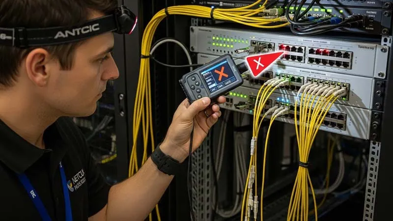
Problem 3: Switch Indicator Turns Red After Inserting Optical Module
Cause and Solution
This issue is usually caused by it incompatibility. Check the manufacturer information through the device management interface. If incompatibility is confirmed, replace the optical module immediately.
Problem 4: Interface Alarm Appears After Optical Module Installation
Recommended Action
Check whether it operating parameters, interface status, and signal reception are normal. Then inspect or replace the fiber jumper and optical module. After replacement, observe the alarm indicator status carefully.
Problem 5: Optical Link Loss Increases or Link Fails
Causes
- Dust-contaminated optical module ports
- Polluted fiber connector end faces
- Scratched pigtail end faces
- Poor-quality fiber connectors
Solutions
Clean optical ports using alcohol-dipped cotton swabs. Meanwhile, wipe fiber connector end faces with professional cleaning paper before reinsertion.
Problem 6: Electrostatic Damage to Optical Module
Prevention Measures
Wear anti-static gloves and shoes when handling optical modules. Moreover, ensure proper grounding and use anti-static packaging during storage and transportation.
Professional Methods for Diagnosing Optical Module Faults
- Visual Inspection
First, inspect the optical module appearance for physical damage, cracks, missing components, poor solder joints, or burn marks.
- Parameter Comparison Method
Next, compare voltage, resistance, and waveform parameters between a normal it and the suspected faulty one, both in powered and unpowered states.
- Component Replacement Method
If abnormal parameters are detected, replace suspected components with known good ones of the same model. Then, retest parameters to confirm recovery.
- Fault Area Localization
Based on failure symptoms, determine the faulty circuit area. For example, low optical power usually indicates a transmission-side issue, while poor sensitivity often relates to the receiving circuit.
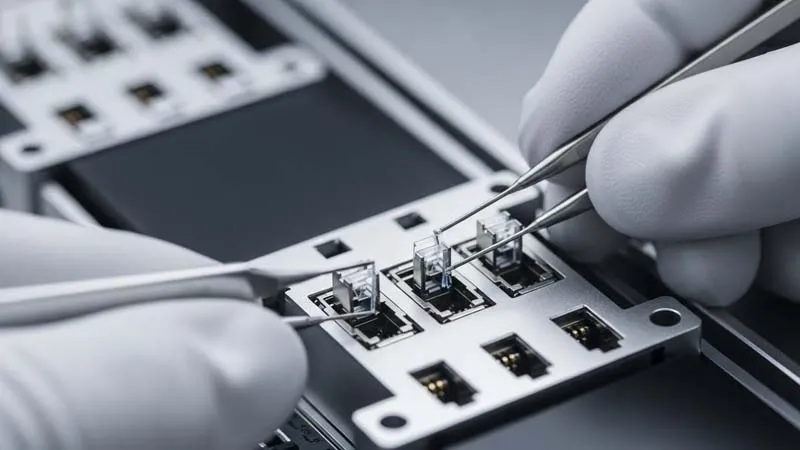
- Structural Analysis of Optical Modules
It mainly consists of TOSA, ROSA, and a PCBA board. Fault identification can be achieved by:
- Testing TOSA and ROSA separately on a component test board
- Measuring pin voltages and continuity using a multimeter
- Observing parameter changes such as it, bias current, and operating current
These methods help isolate faulty components efficiently.
Conclusion: Reducing Optical Module Failures Through Knowledge and Quality
By thoroughly understanding common optical module problems and their solutions, engineers can identify failures faster and resolve them more effectively. In addition, selecting optical modules, switches, and fiber jumpers with high reliability and stable performance significantly reduces failure probability.
Ultimately, combining professional troubleshooting skills with high-quality it is the most effective way to ensure long-term network stability and performance .